
Lasers for Machine Vision: Selection Criteria


A projected line can look sharp to an operator and still produce unreliable camera measurements. The center may saturate, the ends may fade, or the line may broaden when a taller part enters the field of view. Selecting a Machine Vision Laser therefore starts with the image and measurement requirements, rather than the brightest visible beam or the highest optical power. The source, target surface, camera, optics, exposure, and mounting geometry work together. A useful specification describes those conditions clearly enough that candidate lasers can be tested under the same constraints and judged against the same acceptance criteria.
Selection at a glance: Define the inspection task and height range; match wavelength to the target and camera; specify usable line geometry; balance power with exposure; then validate synchronization, thermal behavior, and measurement repeatability in the assembled system.
Define the Inspection Task Before Specifying the Laser
Presence Detection, Profile Measurement, and Defect Inspection
Presence detection asks whether a feature exists in an expected location. Profile measurement requires a stable relationship between image position and physical geometry. Defect inspection may depend on intensity changes, height information, or a combination of both. These tasks place different demands on the projected feature and image processing.
For example, a broad line might be adequate for a simple presence check but unsuitable for resolving a narrow groove. Conversely, an extremely fine line may not remain sufficiently narrow throughout a large height range. Specify the smallest relevant feature and the required measurement behavior before choosing an optical configuration.
Field of View, Height Variation, and Working Distance
Record the camera’s field of view, the space available for the laser, the nominal projection distance, and the nearest and farthest target positions. Distinguish laser-to-target distance from camera-to-target distance. Both affect system design, but they are not the same specification.
Include part tolerances, conveyor movement, fixture variation, and changes between product sizes. A module tested only at the nominal plane may perform poorly at the boundaries. For triangulation, camera and laser angles also influence sensitivity, visible surfaces, and shadows.
Target Motion, Exposure Time, and Required Repeatability
Moving targets limit exposure time if motion blur must remain small. A shorter exposure generally collects fewer photons, which changes the required illumination. Determine whether the camera uses a global or rolling shutter and how illumination will overlap the relevant exposure interval.
Separate resolution, repeatability, and accuracy. A camera can display many pixels without delivering an accurate physical measurement. Calibration quality, geometry, surface behavior, and mechanical movement all contribute. The machine vision laser should be evaluated through the final measurement output, alongside the image itself.

Select Wavelength for the Surface and Camera
The useful signal depends on more than emitted power. Target reflectance, scattering, transmission, camera sensitivity, lens transmission, and filter transmission all affect the detected light. An apparently dark material can respond differently at another wavelength; a visually bright beam may fall in a less favorable region of the camera’s response.
Compare candidate wavelengths on representative surfaces, including coatings and finish variations. Red, green, blue, and infrared options each have possible uses. None is automatically the correct choice for every metal, polymer, or organic material. Strong surface reflection and light penetrating beneath a translucent surface create different imaging problems and may require different responses.
Human visual brightness should not drive a camera-based purchase. The eye and camera have different spectral responses. An infrared beam may be invisible to an operator but detectable by a compatible camera, while an IR-cut filter can prevent that same camera from receiving a useful signal. Confirm the complete optical path.
Ambient light adds background signal. A suitable bandpass filter can improve contrast, but its passband must match the laser and operating conditions. Filter behavior can change with incidence angle, and narrow filtering requires attention to source wavelength variation. Test the filter with the actual lens and mounting arrangement rather than treating its nominal center wavelength as sufficient.
Record exposure, camera gain, aperture, and filtering during wavelength comparisons. Automatic camera settings can disguise a weak signal or make one candidate appear stronger for unrelated reasons. Keeping these conditions controlled makes the comparison meaningful.
Specify the Projected Line Across the Full Measurement Range
Line Width and Depth of Focus
A line-width value is incomplete without its measurement definition, target distance, and position along the line. Full width at half maximum and a width measured at 1/e² intensity describe different portions of the profile. Comparing them as equivalent can produce a misleading shortlist.
A very narrow focused line usually involves a trade-off with the distance over which the line remains suitably narrow. Specify the acceptable width across the full height range, not merely the minimum achieved at focus. The camera’s viewing angle and pixel scale further influence how that projected width appears in the image.
Fan Angle and Usable Line Length
For ideal symmetric fan projection onto a perpendicular plane, approximate line length is twice the projection distance multiplied by the tangent of half the fan angle. This geometric estimate helps establish coverage, but it does not describe usable intensity, edge quality, or oblique-target distortion.
As an illustrative calculation, a 60° full fan angle at 100 mm gives a geometric line length of about 115 mm. That is a geometry example, not a product performance claim. Confirm whether the full illuminated length satisfies the required brightness and focus conditions before using it as the inspection width.
Uniformity, Straightness, and Edge Quality
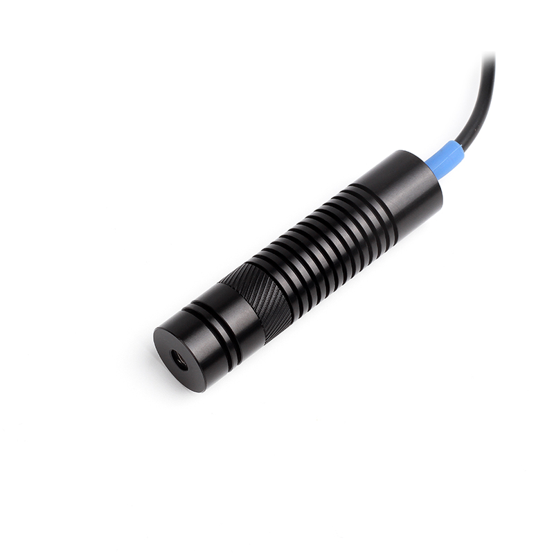
MXTLASER’s Uniform Line Laser represents a line-projection option for industrial image processing. For a candidate configuration, request the intensity profile across the usable length. A single uniformity percentage needs a definition, test distance, included line region, and detector method to be comparable.
Straightness also needs a stated reference and evaluation length. A small percentage applied over a long line can correspond to a significant physical deviation. Include the line’s orientation relative to the module body if alignment to a mechanical datum matters.
A Telecentric Line Laser may be relevant where projection geometry must be controlled over a defined range. Confirm the actual optical behavior and supported field. Telecentric illumination does not automatically make the camera telecentric, remove every occlusion, or eliminate the need for calibration.
Balance Optical Power, Exposure, and Synchronization
Choose a Machine Vision Laser that provides sufficient signal during the available exposure without saturating the sensor on the brightest acceptable surface. Evaluate both ends of the operating range: the weakest useful return and the strongest reflection. A source that works on one nominal sample can fail on production variation.
Total optical power is distributed over a line or pattern. A longer line generally leaves less power available per unit length when other conditions remain comparable. Reducing line length to the required field can sometimes improve usable signal without increasing total output. However, optical losses and the detailed distribution still require measurement.
CW operation provides continuous illumination. TTL control switches supported modules between defined states, while analog modulation can adjust output within a specified operating range. Confirm signal levels, polarity, input impedance, response time, and bandwidth. The label “TTL” alone does not guarantee compatibility with a controller output.
Switching frequency is not the same as minimum useful pulse duration. Rise and fall times, delays, driver behavior, and camera timing determine the effective illuminated interval. For short exposures, inspect image consistency across repeated triggers. A rolling-shutter arrangement may produce bands if illumination timing does not cover the required rows.
Speckle is another limitation. Coherent light scattered from a rough surface can form granular intensity variations that affect feature extraction. It should be distinguished from electronic noise, saturation, and simple underexposure. Increasing laser power does not remove speckle, and any mitigation method must be validated for the measurement.
Likewise, a shadowed region may receive no useful illumination or may be hidden from the camera. Additional power cannot resolve that geometric obstruction. Changing viewing angle, projection angle, part presentation, or the number of views may be necessary.
Validate the Machine Vision Laser in the Actual System
Check the selected configuration’s supply requirements and modulation interface before installation. Confirm connector pinout, grounding, cable arrangement, and permitted power sequencing. Establish a suitable thermal path and avoid clamping forces that could distort the housing or shift optical alignment. Protection features must be confirmed for the specific module.
Environmental requirements should reflect the mounting location. Ambient temperature, vibration, dust, moisture, and nearby process contamination can affect performance. A module enclosure rating does not automatically apply to unsealed connectors, a modified housing, or the assembled machine. Verify the complete installation.
Validation item | Test condition | What to record |
|---|---|---|
Signal range | Darkest and brightest representative surfaces | Line visibility, background, saturation |
Focus and coverage | Minimum and maximum part heights | Usable length, width, missing regions |
Measurement performance | Known reference geometry and repeated parts | Bias, repeatability, outliers |
Timing | Actual exposure and trigger sequence | Missed lines, banding, frame variation |
Thermal behavior | Startup through normal operating temperature | Output variation, line position, measurement drift |
Mechanical stability | Normal machine motion and vibration | Alignment changes and measurement variation |
Define pass criteria before comparing samples. Otherwise, the test can drift toward whichever image looks most attractive. A practical acceptance record includes reference dimensions, permitted error, repeatability, usable field, camera settings, ambient conditions, and the evaluated module configuration.
Use representative production samples rather than a single convenient target. Include finish variation, curved regions, steep slopes, and any expected contamination. If one parameter changes during testing, document it. Traceable settings make it easier to distinguish an optical improvement from a software adjustment.
Laser safety belongs in system validation. Accessible emission, wavelength, geometry, reflections, operating modes, and maintenance access affect the assessment. Do not infer an eye-safe system from total power alone or assume that pulsed operation automatically reduces the classification. Market-specific requirements need evaluation for the finished installation.
Conclusion
A suitable Machine Vision Laser produces a usable and stable image throughout the actual operating range. The decisive evidence is consistent feature extraction and measurement performance across target variation, motion, and temperature. MXTLASER manufactures laser-based light sources, including line-projection options for machine vision. Evaluate any proposed configuration through a documented acceptance test that includes the camera, optics, mounting, and processing method. A clear specification and representative trial provide a stronger basis for selection than isolated claims about power, minimum line width, or nominal uniformity, especially when the production environment differs from laboratory conditions.
Frequently Asked Questions
Can a Machine Vision Laser work with a color camera?
Yes, if its wavelength and signal are compatible with the camera. A color filter array can change sensitivity and sampling compared with a monochrome sensor. Test the intended image-processing channel and any installed optical filters.
How should line uniformity be compared between suppliers?
Request the definition, evaluated line region, working distance, optical setup, and measured profile. Two percentages obtained through different methods may describe different behavior. Compare candidates using one consistent test where possible.
Why does the laser line disappear on some areas of a part?
Possible causes include low reflectance, unfavorable reflection direction, occlusion, transparency, poor focus, or insufficient exposure. Inspect the geometry and raw image before increasing power; several of these causes require a different solution.
Can a narrowband filter replace additional laser power?
It can reduce unwanted background and improve contrast when the laser signal passes efficiently. It cannot recover a signal blocked by geometry or compensate for incompatible wavelength transmission. Verify performance across the field and temperature range.
Which specifications should accompany a sample request?
Include target samples, camera information, working-distance range, field width, required line width, exposure, motion, control interface, mounting constraints, and acceptance criteria. State which conditions are fixed and which can be adjusted during development.