

Standard LED or halogen lighting often falls short in modern manufacturing. High-speed, sub-millimeter 3D profiling and low-contrast surface inspections demand superior illumination. You need a more robust optical solution to catch microscopic defects reliably. Integrating a Machine Vision Laser introduces unparalleled precision to automated inspection lines. However, it requires careful navigation of optical constraints. Thermal management and strict safety compliance also demand your attention. Engineers frequently underestimate these integration complexities, leading to costly deployment delays.
This guide provides technical buyers and integration engineers with an evidence-based framework. We will explore how to specify, evaluate, and shortlist the right optical systems. You will learn actionable strategies to maximize inspection accuracy. By following these steps, you can deploy reliable machine vision architectures seamlessly.
Key Takeaways
Application Dictates Optics: The choice between point, line, and pattern projection relies heavily on the specific inspection task (e.g., 3D triangulation vs. scatter measurement).
Material Interactions Matter: Wavelength selection (e.g., blue vs. red lasers) must be matched to the target material's absorption and reflectivity rates to prevent optical noise.
Uniformity is Non-Negotiable: For measurement accuracy, structured light applications require Powell lenses or specialized optics to ensure uniform intensity distribution across the laser line.
Safety Compliance Influences System Costs: Implementing Class 3B or 4 lasers requires robust safety enclosures and interlocks, significantly impacting overall system footprint and costs compared to Class 2/2M alternatives.
When to Mandate a Machine Vision Laser Over Standard Illumination
Optical selection drives the reliability of automated inspections. Engineers must clearly define the business problem before upgrading hardware. Scenarios exist where standard diffuse lighting yields unacceptable false-reject rates. Traditional lights also fail to capture depth or Z-axis data accurately. You must identify these specific capability gaps to justify an optical upgrade.
Standard illumination struggles against high ambient light. Diffuse LEDs often create washed-out images on factory floors. Shadows obscure critical edge details during complex topographical scans. When contrast levels drop, vision algorithms fail. This triggers unnecessary manual reviews and slows production throughput.
You can determine the need for a laser upgrade by evaluating specific success criteria. The integration becomes necessary when your project requires the following capabilities:
Requirement for micrometer-level topographical mapping to verify precise part geometries.
Need to penetrate translucent materials or overcome extreme ambient factory lighting.
High-speed inline inspection requiring brief, intense illumination to freeze rapid motion.
Despite these benefits, you must perform a skeptical check. Laser systems fundamentally add mechanical and software complexity. They require strict safety protocols and precise mounting. If basic 2D contrast imaging solves the problem reliably, standard LEDs remain the superior choice. You should only mandate coherent light when physics dictates its necessity.
Core Laser Applications In Machine Vision (Use Cases & Outcomes)
3D Laser Triangulation (Profilometry)
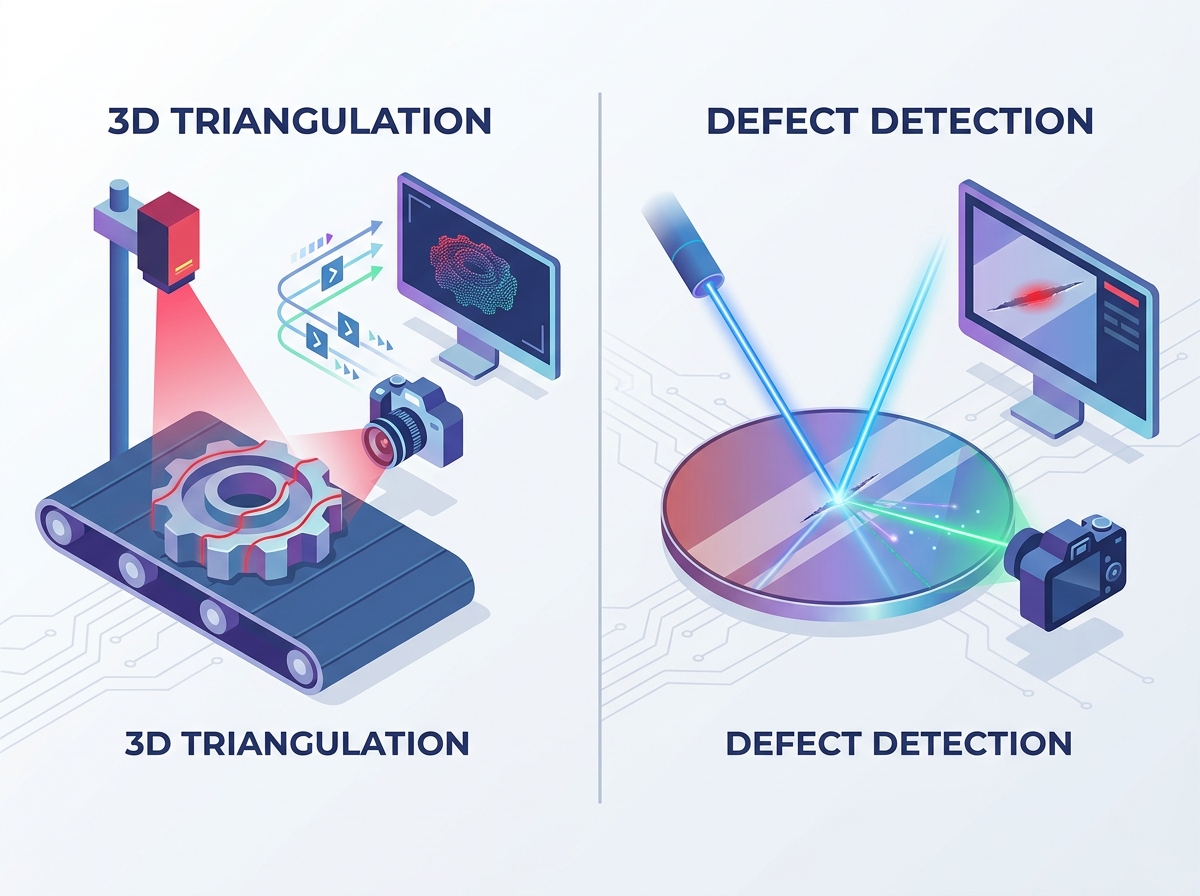
3D profilometry relies on structured light to map spatial coordinates. The mechanism involves projecting a thin line onto a moving target. A skewed camera captures the resulting deformation. Algorithms then calculate the exact 3D geometry of the object based on this optical displacement. Integrating a Uniform Line Laser ensures optimal accuracy for these geometric calculations.
This approach delivers highly actionable outcomes. Manufacturers use it for exact volume measurement and coplanarity checks. PCB inspections rely heavily on triangulation to ensure solder joints sit flush. Dimensional gauging becomes automated, removing human error from the quality control loop.
Defect Detection on Highly Reflective Surfaces
Inspecting glossy materials presents unique challenges. Standard lighting reflects directly back into the camera lens, blinding the sensor. Darkfield laser scattering solves this issue. The mechanism projects a low-angle beam across the surface. Any microscopic scratch on glass or polished metal scatters the light upward. The camera captures only these isolated scatter events.
This technique eliminates glare-induced false positives. Typical diffuse lighting struggles on silicon wafers and machined aluminum. Darkfield scattering highlights only true defects. You achieve much higher confidence in automated sorting routines.
Precision Alignment and Robot Guidance
Robotic automation demands exact spatial references. The mechanism utilizes crosshair or complex pattern projection. This visual guide directs automated pick-and-place arms. Welding robots use these optical markers to track seams in real time. The camera identifies the pattern and adjusts the tool path accordingly.
The primary outcomes include significantly reduced cycle times. Robots spend less time hunting for correct positions. The technique also mitigates mechanical drift over long operational shifts. Your automation cells maintain high tolerances without constant manual recalibration.
The following table illustrates a direct comparison between various optical methods and their ideal applications.
Optical Method | Target Surface | Primary Measurement | Typical Industry Use |
|---|---|---|---|
3D Triangulation | Matte / Opaque | Z-Axis Volume & Topography | PCB Inspection, Wood Processing |
Darkfield Scattering | Highly Reflective / Glass | Microscopic Scratches & Particulates | Semiconductor, Screen Manufacturing |
Pattern Projection | Variable Textures | Spatial Alignment & Guidance | Automotive Welding, Pick-and-Place |
Key Evaluation Dimensions for Specifying a Machine Vision Laser
Optical Performance & Beam Shaping
Optical performance directly dictates sensor data quality. You must evaluate line thickness and depth of field (DoF). A thinner line yields higher resolution, but it often reduces the usable DoF. You must balance the focal distance with your required measurement range. Poor beam shaping results in fuzzy edges and inaccurate software calculations.
Uniform intensity remains crucial for measurement reliability. Standard cylindrical lenses produce a Gaussian distribution. This creates bright "hot spots" in the center and dim edges. You must specify Powell lenses for precise structured light applications. Powell lenses manipulate the beam to ensure a perfectly even intensity distribution across the entire projected line.
Wavelength (Color) Selection
You cannot select wavelengths arbitrarily. You must match the wavelength to the target material. Mismatched colors cause optical noise or poor contrast. Engineers must consider absorption and reflection rates. The correct color drastically improves the signal-to-noise ratio in your imaging system.
Red (660nm): Ideal for general opaque materials. It offers excellent sensor sensitivity and remains cost-effective for standard factory applications.
Blue (405nm/450nm): Best for organic, translucent, or highly reflective materials. Blue light penetrates less, creating sharper surface profiles on shiny metals. It also cuts through the intense ambient glow of hot metals in foundries.
Infrared (808nm+): Used when visible light distracts human operators. It also excels in specific organic sorting tasks.
Power Output and Modulation
Specifying output power requires a delicate balance. High power ensures the camera sensor receives enough photons during rapid exposure times. However, excessive power introduces thermal issues and safety hazards. You must balance the output against the specific sensitivity of your machine vision camera.
You also need to evaluate Transistor-Transistor Logic (TTL) modulation capabilities. TTL allows precise strobing. It synchronizes the illumination pulse directly with the camera shutter. This freezes high-speed motion effectively. It also prolongs diode life by keeping the unit off between captures.
Implementation Realities: Mitigating Risks and Optical Artifacts
Theoretical physics often clashes with rugged industrial realities. Integrating coherent light sources introduces specific optical and environmental challenges. You must proactively address these artifacts during the system design phase. Failure to mitigate these risks compromises your entire inspection architecture.
Speckle reduction challenges frequently plague integrators. Coherent light inherently creates speckle patterns. This granularity degrades edge-detection algorithms. Algorithms interpret the speckle as false texture. You must evaluate hardware solutions like diffusers or vibrating optical elements. Software filtering also helps, but it adds processing latency to your inspection loop.
Thermal drift and stability drastically affect measurement repeatability. Temperature fluctuations shift the peak wavelength of the diode. Heat also causes physical expansion in the housing, misaligning the beam. Output power fluctuates as junction temperatures rise. You must prioritize Thermo-Electric Cooling (TEC) for high-precision tasks. Robust passive heatsinking is mandatory for all industrial deployments.
Laser safety classifications demand strict compliance awareness. Integrating higher-power units introduces significant regulatory burdens. Standards like IEC 60825-1 and CDRH regulations dictate mandatory safety features. You must perform a thorough cost-benefit analysis.
Utilizing enclosed Class 1 systems simplifies deployment greatly. These setups shield operators from stray radiation. Conversely, open Class 3B or Class 4 setups require extensive facility modifications. You will need interlocked doors, warning beacons, and specialized operator training. These compliance measures increase your overall project footprint.
Shortlisting Logic and Vendor Evaluation Framework
Selecting the right hardware partner matters as much as the technical specifications. You need a vendor evaluation framework to separate reliable manufacturers from mere component resellers. A structured shortlisting logic prevents costly late-stage integration failures. Always validate vendor claims before committing capital.
Prototyping availability serves as a crucial initial filter. You should ask if the vendor provides loaner units. Testing specific wavelength and material interactions in your facility is vital. You cannot rely solely on datasheet specifications. Secure hardware for real-world testing before requesting final CAPEX approval.
You must decide between OEM customization and off-the-shelf products. Modular, plug-and-play units work well for standard conveyor setups. They offer quick replacement times during maintenance. However, tight-clearance OEM integrations often require custom PCB-level diodes. Discuss these form-factor constraints with your vendor early.
Longevity and Mean Time Between Failures (MTBF) dictate operational uptime. Request the manufacturer's data on diode lifespan. Ensure the data reflects industrial operating conditions. High vibration, intense heat, and heavy dust degrade optical components rapidly. Verify the IP ratings match your factory environment exactly.
Your next-step actions should focus on empirical validation. We recommend conducting a comprehensive Proof of Concept (PoC). Use the actual target material and your chosen camera sensor. Validate the Signal-to-Noise Ratio (SNR) physically. This hands-on testing provides the confidence needed before locking in the final system specification.
Conclusion
The successful deployment of coherent optical systems bridges a critical gap. It connects theoretical optical physics with rugged industrial realities. Careful planning prevents common integration failures.
Match your wavelength specifically to material absorption rates to maximize image contrast.
Specify Powell lenses over cylindrical options to ensure uniform line intensity.
Implement robust thermal management to prevent wavelength drift and maintain measurement accuracy.
Evaluate safety classifications early to avoid unexpected compliance delays and infrastructure modifications.
Specifying the right optics, thermal controls, and safety class dictates your final system accuracy. It also ensures long-term operational efficiency. Encourage your engineering teams to initiate a feasibility study immediately. Request sample testing for your specific use case to validate these concepts in practice.
FAQ
Q: What is the difference between a standard laser and a machine vision laser?
A: Standard options act as simple pointers. Machine vision alternatives feature precise beam shaping to eliminate optical distortion. They generate uniform lines using specialized optics like Powell lenses. They also include TTL modulation features for exact camera synchronization, ensuring perfect timing for high-speed automated inspections.
Q: Why are blue lasers becoming more common in 3D scanning?
A: Blue light features a shorter wavelength compared to red light. This limits the depth of material penetration. It creates much sharper surface profiles on translucent plastics and highly shiny metals. It also prevents the internal scattering that causes fuzzy edge detection in inspection software.
Q: How do I choose the correct fan angle for a laser line generator?
A: You must calculate the trigonometric relationship between three elements. First, determine your available working distance. Next, define the required line length to cover the object. Finally, match this to the camera's Field of View. The correct fan angle projects the exact line length at your specific working distance.
Q: Are laser speckles avoidable in machine vision?
A: Speckle remains fundamental to coherent light physics. You cannot avoid it entirely. However, you can minimize it effectively. Engineers use specialized diffusers, vibrating optical elements, or specific low-coherence diodes. Advanced software filtering algorithms also help smooth out the granular noise before geometric calculations occur.